Created At
Nov 29, 2018
Created At
Nov 29, 2018
Last Update
Dec 14, 2018
Platforms
HC 2, HC Lite
Views
10735
Download
89
 What is home automation? In short: it is a clever integration of technology and services, to control your home devices for a better quality of life. A home automation system uses a variety of sensors and actors. A sensor makes an observation and can control one or more actors. Actors make a circuit or send out a signal.
Home automation is a step toward what is referred to as the "Internet of Things," in which everything has an assigned IP address, and can be monitored and accessed remotely.
The Jablotron 100 alarm system has a variety of newly developed functionalities and modules that go beyond generating alarms. Thus, in addition to complex security projects, the 100 system platform facilitates a.o. access control and home automation. In this article we describe how a Jablotron 100 system can be connected to a Fibaro (Z-Wave protocol) automation system.
An alarm system monitors your belongings against burglary and / or fire. The Jablotron alarm system offers intelligent functionality with a wide range of sensors and modules. It is therefore possible and value added to connect the alarm system with a home automation system like Fibaro. This allows you to achieve various situations;
Situation:
the door is forced
Alarm system:
detects a burglary (attempt) and gives an alarm.
Home Automation:
lights flash in and around the property to deter intruders and alert neighbors.
Situation:
there is a fire in the pantry. The dryer has shorted.
Alarm system:
detects via the smoke alarm and a fire alarm displays.
Home Automation:
all lamps are turned on in the house and illuminate the escape route. The ventilation, heating and power of all risky electrical equipment is switched off.
Situation:
it is dark and you enter the house through the front door.
Alarm system:
magnetic contact detects that the front door is opened. The alarm system is activated with an entrance / exit delay.
Home automation:
the home automation system knows that the alarm is still active (there is no one at home) and that it is dark, it is after sunset. The Jablotron sensor on the front door activates a scene in the home automation system. The lighting in the main hall and living room are switched on. After 5 minutes, the light in the hall automatically switches off. This way you have 'coming home' lighting function, as you perhaps might know from automobiles.
The possibilities and combinations are almost infinite. You can fully personalize your own wishes.
The link actually works very simple. The Jablotron 100 system, depending on the model, has 16 or 32 programmable outputs (the 101K resp. 106K). Almost every event or state of the alarm system and its associated sensors (or combination thereof) can be assigned to a programmable action for: ON or OFF. For example, if the alarm system is activated then output PG8 can be put to status: ON. These actions can be configured with the supplied F-link software and will be discussed later in this article.
The home automation system then reads these outputs and can perform a number of actions based on one or more outputs (the state of a PG), this is called a 'scene'. Thus, ON and OFF 'trigger' a different scene in the automation system.
In order not to make it too complex, we have in this Example 2 activities;
1. The alarm is being set: armed.
2. An alarm is triggered.
In this example we will use a home automation system in which the sensors and actuators via a wireless communication protocol (Z-Wave) data exchange.
PAY ATTENTION:
The alarm system has a power supply of 230-240V and a 12V battery. Improper or careless handling can cause equipment damage or injury. Working under stress and making a short circuit is to be avoided at all times! Damage caused by negligence or against the guidelines of a supplier, not covered by the warranty.
Disconnect the power and battery. Make sure the alarm system is unset and in service mode.
The JA-101 or JA-106 controls the JA-118N module. The Jablotron JA-118N makes contact depending on its PG output status, then the Fibaro universal sensor detects an open or closed contact. Depending on the status of the contact 1 and contact 2, a scene can be started / stopped. The alarm system can only transmit a status to the automation system, not vice versa. Here you have additional modules required and is not addressed in this article.
Connect the JA-118N to the bus of JA-101 or JA-106 (red - yellow - green - black). There may already be some wired connections in the bus, multiple wires can be connected to the bus connector (see Figure 1).
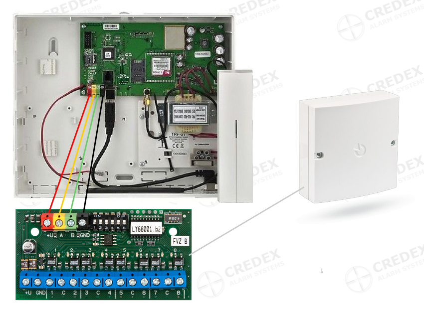
Figure 1: JA-101 control panel + JA-118N: Connecting the bus connectors (red - yellow - green - black).
Follow the steps below for connecting the JA-100 control panel and Fibaro (see Figure 2):
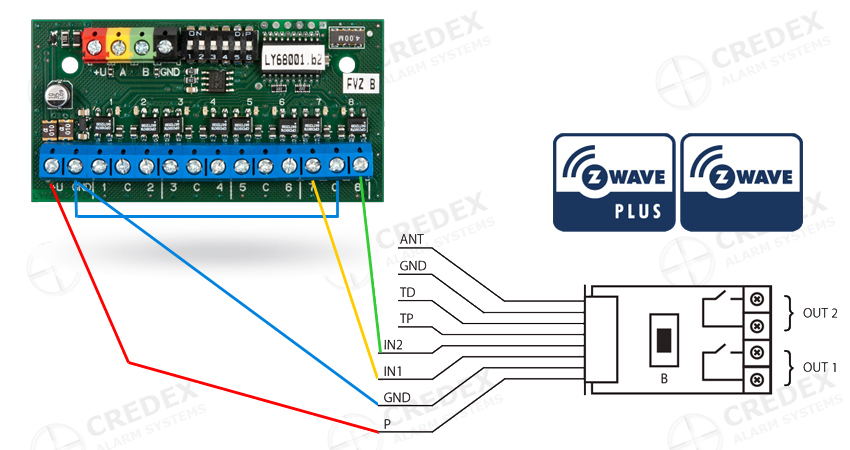
Figure 2: Wiring schedule.
In the F-Link program you now define the programming operations. Start F-Link and go to the 'PG outputs' tab.
1. Give PG15 and PG16 a logical name and description.
PG15: will notify you 'if there is an alarm' and activates output 7 on the JA-118N, so we put in the description Output 7.
PG16: will notify you 'if the alarm is set' and activates output 8 on the JA-118N, the description is Output 8.
![]()
Figure 3: Configuring PG's in F-Link.
2. Press the button 'Activation' to define when PG15 (or PG16) have to be active and for which sections.
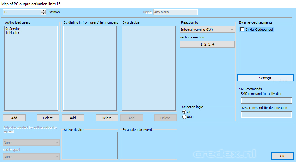
Figure 4: Activation configuration for PG15.
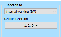
Figure 5: Section selection for PG15.
3. On the right side of the figure 4 screen you will now see 'Reaction to' and 'Section selection'. PG15 will react to 'Internal warning (IW)' for sections 1, 2, 3 and 4. So in the event of an alarm in any section PG15 is active and we have linked it (via the switches on the JA-118N) to Output / output 7.
4. Press 'OK'. We will do the same for PG16, but then: 'Reaction to: Any set'.
If the alarm is set in the selected areas, PG16 will become active. PG16 is linked to Output / output 8.
5. Press OK.
6. We will now check whether the JA-118N works by pressing 'TEST' in FLink for PG15 / PG16 (see figure 4).
7. If all works well, a led on the JA-118N will enlight for PG15 / PG16.
If not, check the bus wiring and the DIP switch setting on the JA-118N module. Before you modify the wiring or installation, make sure the control panel is in service mode and the power is switched off (disconnected the 230V power supply and battery).
8. If the JA-118N card responds to the TEST button in F-link, and the Fibaro modules are connected to your home automation system: you should have two additional devices which are seen as sensors. The names and symbols of these sensors may vary by system.
Example of two sensors in the home automation system:
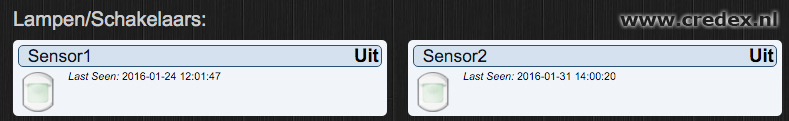
Figure 6: The input of the FGBS-001 are seen as sensors in the home automation system.
9. We can now read if these two devices are 'On' or 'Off'. You are now able to assign a simple instruction to these sensors. Refer to the capabilities of your system for exact details. However, it will not deviate much.
10. In the figure below you will see some lights and appliances attached to an instruction, 'scene'. These devices are switched On or Off as the scene 'alle basis verlichting uit' ('all basic lighting off )' is addressed.
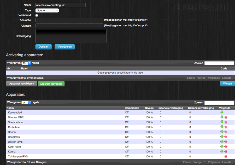
Figure 7: Example of a scene.
In the above picture mentioned devices ('apparaten') are already existing devices and switches of an automation system (Domoticz with Z-wave). For example, a lamp includes a smart wireless socket to receive a command to activate or deactivate. These are all 'actors'.
11. The final step is to carry out the scene as 'Sensor1' or 'Sensor2' get the status 'ON' via the alarm system. This is possible in almost any home automation system, refer to the documentation. Many systems have a possibility to make a program via simple blocks.
IF [sensor1] switches on, DO lamps SCENE [All basic lighting off] off.
12. It looks like this:
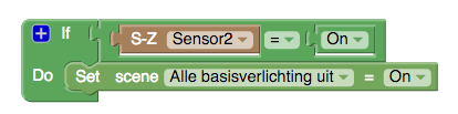
Figure 8: Perform a scene when sensor 2 has the status ON.
13. You can be as specific as you like by adding conditions as times / days or the status of other switches / actuators.
14. If two statuses / PG's are insufficient for the number of scenes, you could connect extra fibaro FGBS-001 modules to the JA-118N. So you can also create a PG for a door sensor. This can switch on the light in the hallway when the door opens.
For the beginner:
Take a look at the Fibaro website www.fibaro.nl
For our Dutch website, look here: Jablotron 100 alarmsysteem
Succes!
Credex Alarm Systems
www.credexalarmsystems.eu